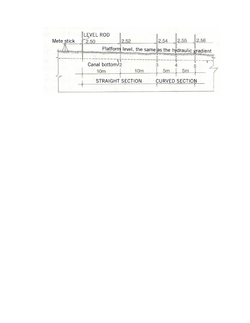
Slope: 2/1000 (two per thousand), which means that every
10 m horizontally there is a difference in elevation of 2 cm and every
5m horizontally there is a difference in elevation of 1 cm.
Fig. 12
Lining the Canal
This consists of placing a layer of concrete (Concrete compressive strength, f'c:
175 kg/cm2) on the bottom and side walls of the canal, forming a uniform
thickness and a polished finish. Level the finished work to the thickness
determined by the wooden frame.
Procedure:
a) Fill with rubble every 10m on a straight section and every 5m or so
on a curved section, taking the design slope into account.
Use a mete stick to achieve more precision.
b) Fitting the wooden frames. The guide frames or master frames will
be placed in each template, properly aligned, squared and plumbed
with respect to the centre line of the canal, fixing them with stakes
and No. 16 wire hammered into both banks. Subsequently, the
construction worker will fit intermediate wooden frames every 2.50m
in straight sections, checking the required slope with a level hose.
(0.5cm difference in elevation). Each one will be aligned, squared, plumbed
and fixed.
11